Pneumatic actuators are mechanical devices that convert compressed air energy into linear or rotary motion. They are widely used in industrial automation, manufacturing, robotics, and process control systems due to their simplicity, reliability, and cost-effectiveness. This article explores the working principle of pneumatic actuators, their design components, types, and real-world applications, while also addressing their advantages and limitations.
1. Fundamental Working Principle
Pneumatic actuators operate based on the principles of fluid dynamics and thermodynamics. Compressed air, typically supplied at pressures ranging from 40 to 120 psi (3 to 8 bar), serves as the working medium. The actuator transforms the potential energy stored in compressed air into kinetic energy, generating mechanical force and motion.
1.1 Core Mechanism
The actuator’s operation involves three key stages:
- Energy Input: Compressed air is directed into the actuator’s chamber via a control valve.
- Pressure-to-Force Conversion: The pressurized air exerts force on a movable component (e.g., a piston or diaphragm), creating linear or rotary displacement.
- Motion Output: The actuator’s shaft or arm transmits the generated motion to the load, such as a valve, gripper, or conveyor system.
1.2 Thermodynamic Basis
The behavior of compressed air in pneumatic systems adheres to Boyle’s Law (PV = constant at constant temperature) and Charles’s Law (V/T = constant at constant pressure). When air is compressed, its pressure increases, and its volume decreases. Upon release into the actuator, the air expands, performing work on the actuator’s internal components.
2. Key Components of a Pneumatic Actuator
A typical pneumatic actuator comprises the following components:
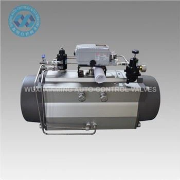
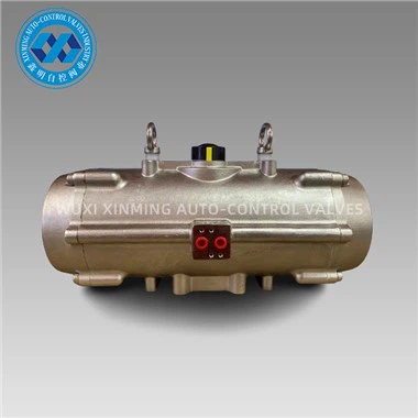
2.1 Cylinder
The cylinder is a hollow, pressure-tight chamber housing the piston or diaphragm. It is usually made of aluminum, stainless steel, or composite materials to withstand high pressures and resist corrosion.
2.2 Piston or Diaphragm
- Piston: A sliding component that moves linearly within the cylinder. Pistons are sealed with O-rings or lip seals to prevent air leakage.
- Diaphragm: A flexible membrane used in diaphragm actuators, which deforms under air pressure to produce motion.
2.3 Actuator Shaft (Stem)
The shaft connects the piston/diaphragm to the external load. Its motion (linear or rotary) is proportional to the applied air pressure.
2.4 Seals and Bearings
- Seals: Prevent air leakage between moving parts. Common materials include nitrile rubber (NBR) and polytetrafluoroethylene (PTFE).
- Bearings: Reduce friction in rotary actuators.
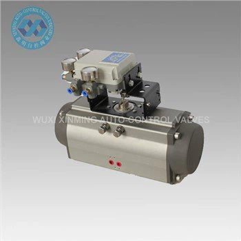
2.5 Control Valve
A solenoid or pneumatic valve regulates airflow into and out of the actuator. It determines the direction and speed of motion.
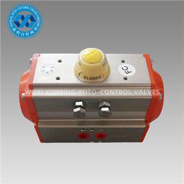
2.6 Position Feedback Sensors (Optional)
Advanced actuators include sensors (e.g., potentiometers or Hall-effect sensors) to monitor position and enable closed-loop control.
3. Types of Pneumatic Actuators
Pneumatic actuators are classified based on their motion type and design.
3.1 Linear Actuators
These produce straight-line motion and are subdivided into:
- Single-Acting Actuators: Compressed air acts on one side of the piston, while a spring returns the piston to its original position. Used in applications requiring fail-safe operation.
-

- Double-Acting Actuators: Air pressure is alternately applied to both sides of the piston, enabling bidirectional motion. These offer higher force output and precise control.
-

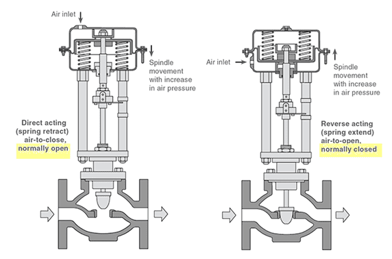
3.1.1 Diaphragm Actuators
A diaphragm separates the air chamber from the actuator body. When pressurized, the diaphragm flexes to move the actuator stem. Commonly used in control valves for throttling applications.
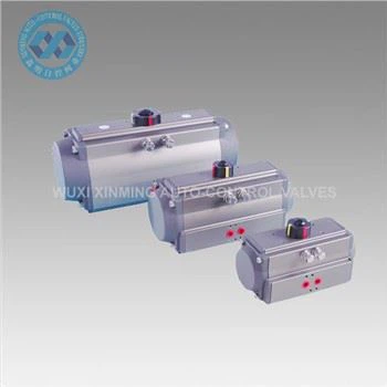
3.2 Rotary Actuators
These generate angular motion and include:
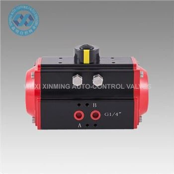
- Rack-and-Pinion Actuators: A piston with a rack gear engages a pinion gear to convert linear motion into rotary motion (typically 90° or 180°).
- Vane Actuators: A rotating vane inside a cylindrical chamber produces torque. These are compact and suitable for low-torque applications.
3.3 Grippers and Specialty Actuators
Pneumatic grippers use jaws actuated by air pressure to grasp objects. They are widely used in pick-and-place robotics.
4. Detailed Working Principle by Actuator Type
4.1 Single-Acting Pneumatic Actuator
- Compressed Air Supply: Air enters the actuator’s inlet port, pressurizing the chamber behind the piston.
- Forward Stroke: The piston moves forward, compressing the return spring.
- Spring Return: When the air supply is cut off, the spring expands, pushing the piston back to its original position.
- Exhaust: The displaced air exits through an exhaust port.
Applications: Clamping, stamping, and emergency shut-off systems where fail-safe operation is critical.
4.2 Double-Acting Pneumatic Actuator
- Forward Stroke: Air is supplied to Chamber A, forcing the piston toward Chamber B.
- Reverse Stroke: Air is redirected to Chamber B, pushing the piston back toward Chamber A.
- Exhaust Cycle: Air from the opposing chamber is vented through exhaust ports.
Applications: High-cycle operations like material handling and valve automation.
4.3 Rack-and-Pinion Rotary Actuator
- Linear-to-Rotary Conversion: The piston’s linear motion drives a rack gear, which rotates a pinion gear.
- Torque Generation: The pinion gear’s rotation produces torque at the actuator shaft.
- Reversal: Reversing the airflow direction rotates the pinion in the opposite direction.
Applications: Valve automation, conveyor diverters, and indexing tables.
5. Control Systems for Pneumatic Actuators
5.1 Open-Loop Control
Basic systems rely on manual or timed valve switching. While simple, they lack precision.
5.2 Closed-Loop Control
Feedback sensors enable real-time adjustments via programmable logic controllers (PLCs) or proportional-integral-derivative (PID) algorithms. This is essential for precision tasks like robotic assembly.
5.3 Proportional Valves
These valves modulate airflow proportionally to an electrical signal, enabling variable force and speed control.
6. Advantages of Pneumatic Actuators
- High Power-to-Weight Ratio: Capable of generating significant force with compact designs.
- Rapid Response: Compressed air allows for fast actuation speeds (up to 1 m/s).
- Safety: Non-flammable and suitable for explosive environments.
- Low Maintenance: Fewer moving parts compared to hydraulic or electric actuators.
- Cost-Effective: Compressed air is inexpensive and widely available.
7. Limitations and Challenges
- Limited Precision: Air compressibility makes precise positioning difficult without feedback systems.
- Energy Inefficiency: Compressing air is less efficient than electric or hydraulic systems.
- Noise and Vibration: Exhaust air can generate noise exceeding 85 dB, requiring silencers.
- Environmental Impact: Air leaks contribute to energy waste and carbon emissions.
8. Applications in Industry
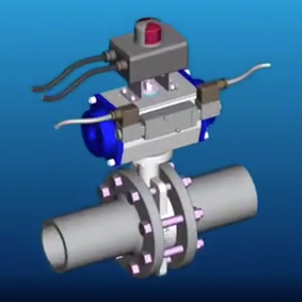
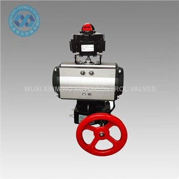
8.1 Valve Automation
Pneumatic actuators control globe, ball, and butterfly valves in oil and gas, chemical, and water treatment plants.
8.2 Manufacturing Automation
Used in assembly lines for tasks like part insertion, welding, and packaging.
8.3 Robotics
Pneumatic grippers and arms enable pick-and-place operations in automotive and electronics manufacturing.
8.4 Aerospace
Actuate landing gear, cargo doors, and thrust reversers in aircraft.
8.5 Medical Devices
Pneumatic systems power surgical robots and ventilators due to their cleanliness and reliability.
9. Future Trends and Innovations
- Smart Pneumatics: Integration with IoT for predictive maintenance and energy optimization.
- Hybrid Actuators: Combining pneumatic and electric systems to leverage the strengths of both.
- Eco-Friendly Designs: Reducing air consumption through improved sealing and valve technology.
10. Conclusion
Pneumatic actuators remain indispensable in modern automation due to their robustness, simplicity, and versatility. While they face competition from electric and hydraulic systems, ongoing advancements in control technology and materials science ensure their relevance in Industry 4.0 applications. Engineers must weigh factors like precision, energy efficiency, and environmental impact when selecting actuators for specific use cases.
If you want to learn more about low-priced products, please visit the following website: www.xm-valveactuator.com