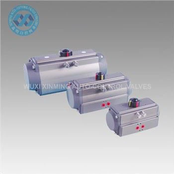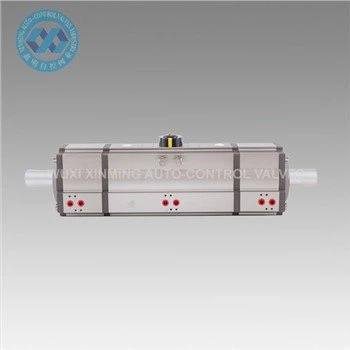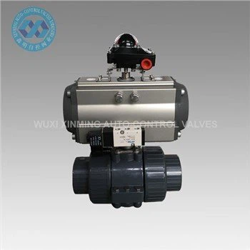
Connection between ball valve and pneumatic actuator
1、 Wiring of solenoid valve
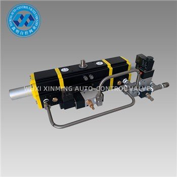
Electromagnetic valve is a key component for controlling pneumatic actuators, which controls the action of the actuator by changing the direction of compressed air flow. The wiring steps for the solenoid valve are as follows:
1. Firstly, confirm that the power supply voltage provided by the control system matches the rated voltage of the solenoid valve.
2. Connect the power cord (usually two wires) of the solenoid valve to the output terminal of the control system. If the solenoid valve has an indicator light, it can also be connected to the power line for monitoring the working status of the solenoid valve.
3. For safety reasons, connect the grounding wire of the solenoid valve to the common grounding point of the control system.
4. Before supplying power to the system, check that all wiring is secure to ensure there is no risk of short circuit.
solenoid valve
2、 Wiring of position sensor
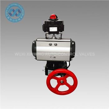
Position sensors are used to monitor the position of pneumatic actuators so that the control system can make corresponding adjustments. The wiring steps are as follows:
1. There are various types of position sensors, such as proximity switches, photoelectric switches, etc. So it is necessary to confirm the output signal type of the sensor (such as PNP or NPN).
2. Connect the signal line of the sensor to the input terminal of the control system. For PNP sensors, the black wire (common wire) is usually grounded, and the blue wire (signal wire) is connected to the input of the control system; For NPN sensors, connect the black wire to the positive power supply and the blue wire to the input terminal.
3. If the sensor has a grounding wire, connect it to the common grounding point of the control system.
4. After power supply, use test buttons or switches to simulate the action of pneumatic actuators and check whether the sensors can output signals correctly.
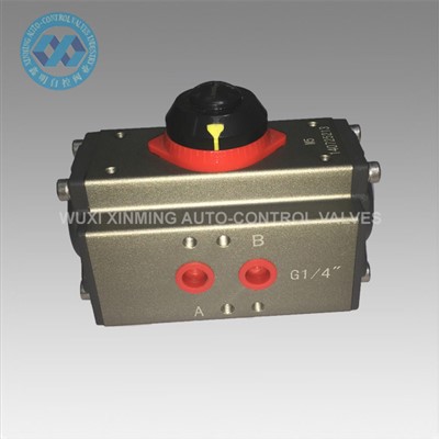
positioner
3、 Wiring of limit switch
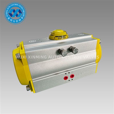
The limit switch is used to stop the movement of the pneumatic actuator when it reaches the preset position. The wiring steps are as follows:
1. The limit switch may be mechanical or electronic, confirm its output signal type.
2. Connect the signal line of the limit switch to the input terminal of the control system. Usually, limit switches have two terminals, one is normally closed (NC) and the other is normally open (NO). Select the appropriate wiring method according to the requirements of the control system.
3. After power supply, manually move the actuator to the limit position and check if the limit switch can output the signal correctly.
If you want to learn more about low-priced products, please visit the following website: www.xm-valveactuator.com